Turbine with variable geometry: principle of operation, device, repair
With the development of turbines for internal combustion engines, manufacturers are trying to improve their consistency with motors and efficiency. The most technically advanced serial solution is a change in the geometry of the inlet. Next, the design of variable geometry turbines, the principle of operation, and maintenance features are considered.
General features
The turbines under consideration differ from the usual ones in the ability to adapt to the engine operating mode by changing the A / R ratio, which determines the throughput. This is a geometric characteristic of the housings, represented by the ratio of the cross-sectional area of the channel and the distance between the center of gravity of this section and the central axis of the turbine.
The relevance of turbochargers with variable geometry is due to the fact that for high and low speeds the optimal values of this parameter differ significantly. So, at a small value of A/R, the flow has a high speed, as a result of which the turbine spins up quickly, but the maximum throughput is low. Large values of this parameter, on the contrary, determine a large throughput and a low exhaust gas velocity.
Therefore, if the A/R is too high, the turbine will not be able to create pressure at low speeds, and if it is too low, it will choke the engine at the top (due to the back pressure in the exhaust manifold, performance will drop). Therefore, on fixed geometry turbochargers, an average A / R value is selected that allows it to operate over the entire speed range, while the principle of operation of turbines with variable geometry is based on maintaining its optimal value. Therefore, such options with a low boost threshold and minimal lag are highly effective at high speeds.
In addition to the main name (variable geometry turbines (VGT, VTG)) these variants are known as variable nozzle (VNT), variable impeller (VVT), variable area turbine nozzle (VATN) models.
The variable geometry turbine was developed by Garrett. In addition to it, other manufacturers are engaged in the release of such parts, including MHI and BorgWarner. The primary manufacturer of slip ring variants is Cummins Turbo Technologies.
Despite the use of variable geometry turbines mainly on diesel engines, they are very common and gaining popularity. It is assumed that in 2020 such models will occupy more than 63% of the global turbine market. The expansion of the use of this technology and its development is primarily due to the tightening of environmental standards.
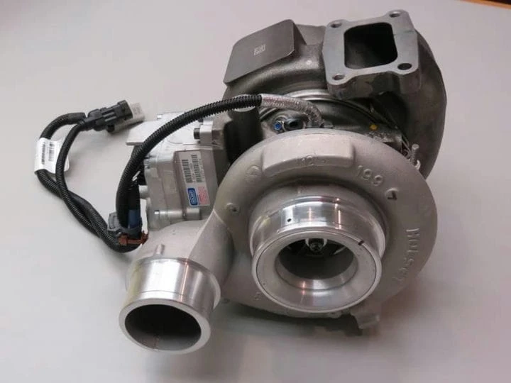
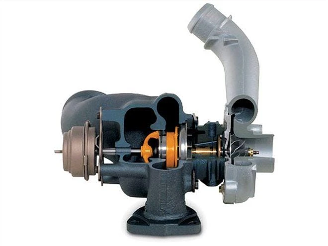
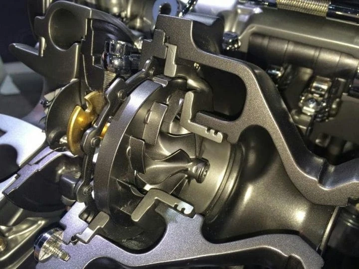
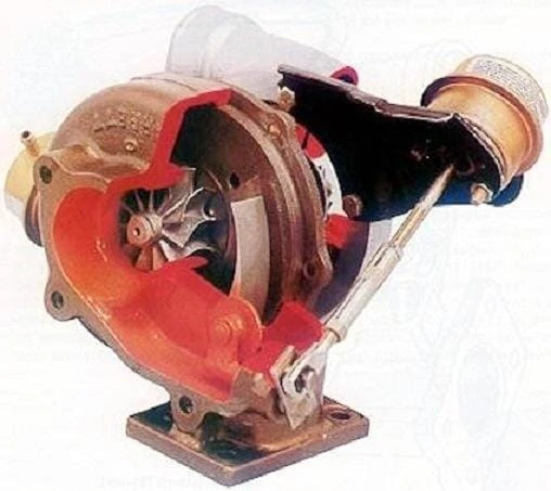
Design
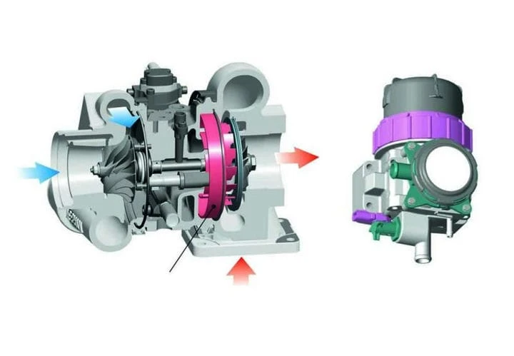
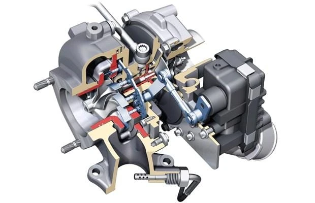
The device of the turbine with variable geometry differs from conventional models by the presence of an additional mechanism in the inlet part of the turbine casing. There are several options for its design.
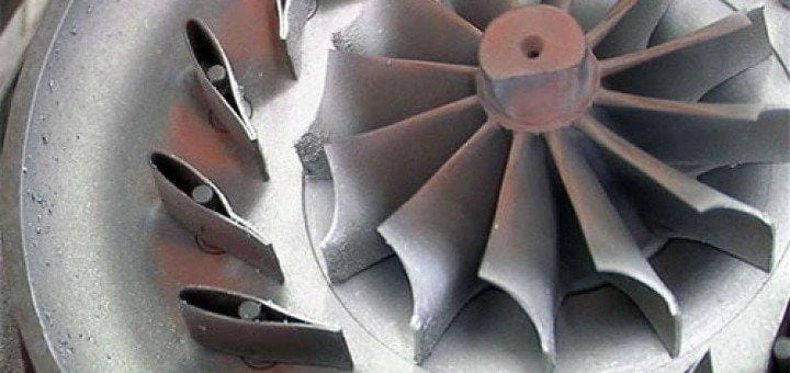
The most common type is the sliding paddle ring. This device is represented by a ring with a number of rigidly fixed blades located around the rotor and moving relative to the fixed plate. The sliding mechanism serves to narrow/expand the passage for the flow of gases.
Since the paddle ring slides in the axial direction, this mechanism is very compact, and the minimum number of weak points ensures strength. This option is suitable for large engines, so it is mainly used on trucks and buses. It is characterized by simplicity, high performance on the “bottoms”, reliability.
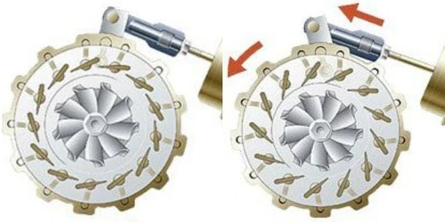
The second option also assumes the presence of a bladed ring. However, in this case, it is rigidly fixed on a flat plate, and the blades are mounted on pins that ensure their rotation in the axial direction, on the other side of it. Thus, the geometry of the turbine is changed by means of the blades. This option is the most efficient.
However, due to the large number of moving parts, this design is less reliable, especially in high temperature conditions. The noted problems are due to the friction of metal parts, which expand when heated.
Another option is a moving wall. It is similar in many ways to the slip ring technology, however in this case the fixed blades are mounted on a static plate rather than a slip ring.
A variable area turbocharger (VAT) involves blades that rotate around a mounting point. Unlike the scheme with rotary blades, they are installed not along the circumference of the ring, but in a row. Because this option requires a complex and expensive mechanical system, simplified versions have been developed.
One of them is the Aisin Seiki Variable Flow Turbocharger (VFT). The turbine housing is divided into two channels by a fixed blade and is equipped with a damper that distributes the flow between them. A few more fixed blades are installed around the rotor. They provide retention and flow merging.
The second option, called the Switchblade scheme, is closer to VAT, but instead of a row of blades, a single blade is used, also rotating around the installation point. There are two types of such construction. One of them involves the installation of the blade in the central part of the body. In the second case, it is in the middle of the channel and divides it into two compartments, like a VFT blade.
To control the turbine with variable geometry, drives are used: electric, hydraulic, pneumatic. The turbocharger is controlled by the engine control unit (ECU, ECU).
It should be noted that such turbines do not require a bypass valve, as due to precise control it is possible to slow down the flow of exhaust gases in a non-decompressive way and pass the excess through the turbine.
Operating principle
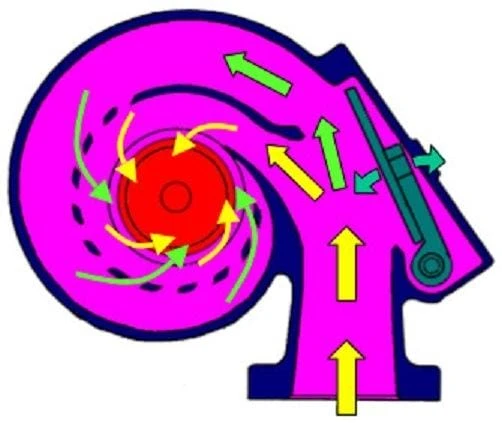
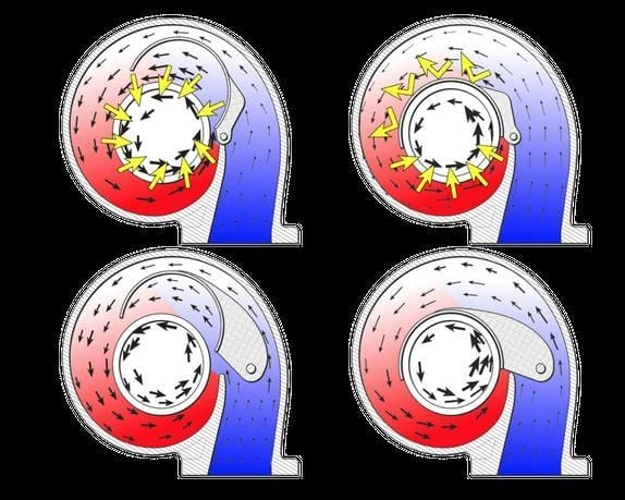
Variable geometry turbines work by maintaining the optimum A/R and swirl angle by varying the cross-sectional area of the inlet. It is based on the fact that the exhaust gas flow velocity is inversely related to the channel width. Therefore, on the “bottoms” for fast promotion, the cross section of the input part decreases. With an increase in speed to increase the flow, it gradually expands.
Geometry Modification Mechanism
The mechanism for implementing this process is determined by the design. In models with rotating blades, this is achieved by changing their position: to ensure a narrow section, the blades are perpendicular to the radial lines, and to widen the channel, they move into a stepped position.
In turbines with a sliding ring and a moving wall, the axial movement of the ring occurs, which also changes the cross section of the channel.

The principle of operation of VFT is based on flow separation. Its acceleration at low speeds is carried out by closing the external compartment of the channel with a damper, as a result of which the gases go to the rotor in the shortest possible way. As the load increases, the damper rises to allow flow through both compartments to expand capacity.
For VAT and Switchblade models, the change in geometry is done by turning the blade: at low speeds it rises, narrowing the passage to speed up the flow, and at high speeds it is adjacent to the turbine wheel, expanding the throughput. Switchblade turbines of the second type are characterized by the reverse order of the blade.
So, on the “bottoms” it is adjacent to the rotor, as a result of which the flow goes only along the outer wall of the housing. As the speed increases, the blade rises, opening a passage around the impeller to increase throughput.
Drive unit
Among the drives, the most common are pneumatic options, where the mechanism is controlled by a piston moving air inside the cylinder.
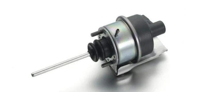
The position of the vanes is controlled by a diaphragm actuator connected by a rod to the vane control ring, so the throat can constantly change. The actuator drives the stem depending on the level of vacuum, counteracting the spring. Vacuum modulation controls an electric valve that supplies a linear current depending on the vacuum settings. Vacuum can be generated by the brake booster vacuum pump. The current is supplied from the battery and modulates the ECU.
The main disadvantage of such drives is due to the difficultly predictable state of the gas after compression, especially when heated. Therefore, hydraulic and electric drives are more advanced.
Hydraulic actuators function on the same principle as pneumatic actuators, but instead of air in the cylinder, a liquid is used, which can be represented by engine oil. In addition, it does not compress, as a result of which such a system provides better control.
The solenoid valve uses oil pressure and a signal from the ECU to move the ring. The hydraulic piston moves the rack and pinion, which rotates the toothed gear, as a result of which the blades are pivotally connected. To transfer the position of the ECU blade, an analog position sensor moves along the cam of its drive. When the oil pressure is low, the vanes open and close as the oil pressure increases.
The electric actuator is the most accurate, as the voltage can provide very fine control. However, it requires additional cooling, which is provided by coolant tubes (in pneumatic and hydraulic versions, liquid is used to remove heat).
A selector mechanism is used to drive the geometry change device.
Some models of turbines use a rotary electric drive with a direct stepper motor. In this case, the position of the blades is controlled by an electronic feedback valve through the rack and pinion mechanism. For feedback from the ECU, a cam with a magnetoresistive sensor attached to the gear is used.
If it is necessary to turn the blades, the ECU provides a current supply in a certain range to move them to a predetermined position, after which, having received a signal from the sensor, it de-energizes the feedback valve.
The engine control unit
From the foregoing, it follows that the principle of operation of turbines with variable geometry is based on the optimal coordination of an additional mechanism in accordance with the operating mode of the engine. Therefore, its precise positioning and constant monitoring is required. Therefore variable geometry turbines are controlled by engine control units.
They use strategies to either maximize productivity or improve environmental performance. There are several principles for the functioning of the BUD.
The most common of these involves the use of reference information based on empirical data and engine models. In this case, the feedforward controller selects values from a table and uses feedback to reduce errors. This is a versatile technology that allows you to apply various control strategies.
Its main disadvantage is the limitations during transients (sharp acceleration, gear changes). To eliminate it, multi-parameter, PD- and PID-controllers were used. The latter are considered the most promising, but they are not sufficiently accurate over the entire range of loads. This was solved by applying fuzzy logic decision algorithms using MAS.
There are two technologies for providing background information: the mean engine model and artificial neural networks. The latter includes two strategies. One of them involves maintaining boost at a given level, the other is maintaining a negative pressure difference. In the second case, the best environmental performance is achieved, but the turbine speed is exceeded.
Not many manufacturers are developing ECUs for variable geometry turbochargers. The vast majority of them are represented by products of automakers. However, there are some third-party high-end ECUs on the market that are designed for such turbines.
General provisions
The main characteristics of turbines are represented by air mass flow and flow rate. Inlet area is one of the performance limiting factors. Variants with variable geometry allow you to change this area. So, the effective area is determined by the height of the passage and the angle of the blades. The first indicator is changed in versions with a sliding ring, the second – in turbines with rotary blades.
Thus, variable geometry turbochargers constantly provide the required boost. As a result, engines equipped with them do not have lag due to the turbine spin-up time, as with conventional large turbochargers, and do not choke at high speeds, as with small ones.
Finally, it should be noted that, although variable geometry turbochargers are designed to operate without a bypass valve, they have been found to provide performance gains primarily at the “lower end”, and at high speeds with fully open blades, not in able to handle large mass flow. Therefore, to prevent excessive back pressure, it is still recommended to use a wastegate.
Advantages and disadvantages
Adjusting the turbine to the engine operating mode provides an improvement in all indicators in comparison with fixed geometry options:
- better responsiveness and performance throughout the entire rpm range;
- smoother torque curve at medium speeds;
- the ability to operate the engine at partial load on a more efficient lean air-fuel mixture;
- better thermal efficiency;
- prevention of excessive boost at high speeds;
- best environmental performance;
- lower fuel consumption;
- extended turbine operating range.
The main disadvantage of variable geometry turbochargers is their significantly complicated design. Due to the presence of additional moving elements and drives, they are less reliable, and maintenance and repair of turbines of this type is more difficult. In addition, modifications for gasoline engines are very expensive (about 3 times more expensive than conventional ones). Finally, these turbines are difficult to combine with engines that are not designed for them.
It should be noted that variable geometry turbines are often inferior to conventional counterparts in terms of peak performance. This is due to losses in the housing and around the supports of the moving elements. In addition, the maximum performance drops sharply when moving away from the optimal position. However, the overall efficiency of turbochargers of this design is higher than that of fixed geometry variants due to the larger operating range.
Application and additional functions
The scope of variable geometry turbines is determined by their type. So, on the engines of cars and light commercial vehicles, options with rotating blades are installed, and modifications with a sliding ring are used mainly on trucks.
In general, variable geometry turbines are most often used on diesel engines. This is due to the low temperature of their exhaust gases.
On light diesel engines, such turbochargers serve primarily to compensate for the loss of performance from the exhaust gas recirculation system.
On trucks, the turbines themselves can improve environmental performance by controlling the amount of exhaust gases recirculated to the engine intake. Thus, with the use of variable geometry turbochargers, it is possible to increase the pressure in the exhaust manifold to a value greater than in the intake manifold in order to accelerate recirculation. Although excessive back pressure has a negative effect on fuel efficiency, it helps to reduce nitrogen oxide emissions.
In addition, the mechanism can be modified to reduce the efficiency of the turbine in a given position. This is used to raise the temperature of the exhaust gases in order to scavenge the particulate filter by oxidizing the stuck carbon particles as a result of heating.
These functions require hydraulic or electric drive.
The noted advantages of variable geometry turbines over conventional ones make them the best option for sports engines. However, they are extremely rare on gasoline engines. Only a few sports cars equipped with them are known (currently the Porsche 718, 911 Turbo and Suzuki Swift Sport). According to one BorgWarner manager, this is due to the very high cost of producing such turbines, due to the need to use specialized heat-resistant materials to interact with the high-temperature exhaust gases of gasoline engines (diesel exhaust gases have a much lower temperature, so turbines are cheaper for them).
The first VGTs used on gasoline engines were made from conventional materials, so complex cooling systems had to be used to ensure acceptable service life. So, on the 1988 Honda Legend, such a turbine was combined with a water-cooled intercooler. In addition, this type of engine has a wider range of exhaust gas flow rates, thus requiring the ability to handle a larger mass flow range.
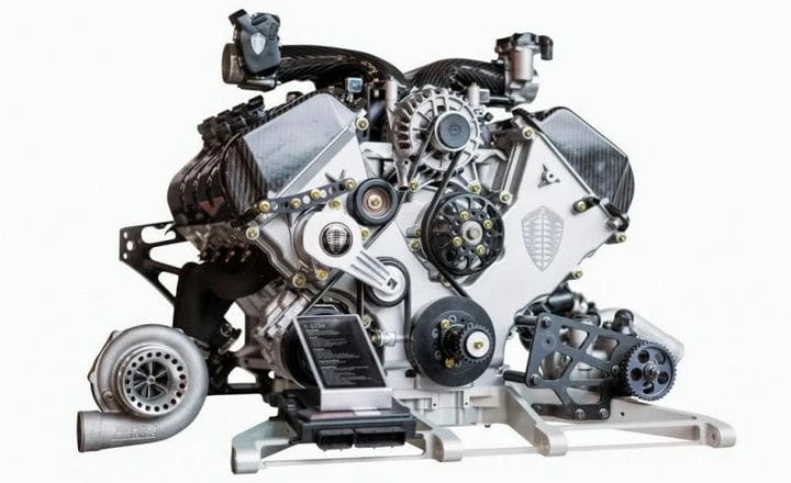
Manufacturers achieve the required levels of performance, responsiveness, efficiency and environmental friendliness in the most cost-effective way. The exception is isolated cases when the final cost is not a priority. In this context, this is, for example, achieving record-breaking performance at Koenigsegg One: 1 or adapting a Porsche 911 Turbo to civilian use.
In general, the vast majority of turbocharged cars are equipped with conventional turbochargers. For high-performance sports engines, twin-scroll options are often used. Although these turbochargers are inferior to VGTs, they offer the same advantages over conventional turbines, only to a lesser extent, and yet have almost the same simple design as the latter. As for tuning, the use of variable geometry turbochargers, in addition to high cost, is limited by the complexity of their tuning.
For gasoline engines, in a study by H. Ishihara, K. Adachi and S. Kono, the variable flow turbine (VFT) was noted as the most optimal among VGTs. Thanks to only one moving element, production costs are reduced and thermal stability is increased. In addition, such a turbine operates according to a simple ECU algorithm, similar to fixed geometry options equipped with a bypass valve. Particularly good results have been obtained when such a turbine is combined with an iVTEC. However, for forced induction systems, an increase in exhaust gas temperature by 50-100 °C is observed, which affects environmental performance. This problem was solved by using an aluminum water-cooled manifold.
BorgWarner's solution for gasoline engines was to combine twin scroll technology and variable geometry design in the twin scroll variable geometry turbine presented at SEMA 2015. Its design is similar to the twin scroll turbine: this turbocharger has a dual inlet and a twin monolithic turbine wheel and is combined with a twin scroll manifold, taking into account the cylinder sequence to eliminate exhaust gas pulsation in order to create a denser flow.
The difference lies in the presence of a damper in the inlet part, which, depending on the load, distributes the flow over the impellers. At low speeds, all the exhaust gases go to a small part of the rotor, and the large part is blocked, which provides even faster spin-up than a conventional twin-scroll turbine. As the load increases, the damper gradually moves to the middle position and evenly distributes the flow at high speeds, as in a standard twin-scroll design. That is, in terms of the mechanism for changing the geometry, such a turbine is close to a VFT.
Thus, this technology, like variable geometry technology, provides a change in the A / R ratio depending on the load, adjusting the turbine to the engine's operating mode, which expands the operating range. At the same time, the design under consideration is much simpler and cheaper, since only one moving element is used here, operating according to a simple algorithm, and heat-resistant materials are not required. The latter is due to a decrease in temperature due to heat loss on the walls of the double casing of the turbine. It should be noted that similar solutions have been encountered before (for example, a quick spool valve), but for some reason this technology has not gained popularity.
Maintenance and repair
The main maintenance operation for turbines is cleaning. The need for it is due to their interaction with exhaust gases, represented by the combustion products of fuel and oils. However, cleaning is rarely required. Intensive pollution indicates violations of the functioning mode, which can be caused by excessive pressure, wear of the gaskets or bushings of the impellers, as well as the piston compartment, clogging of the breather.
Variable geometry turbines are more sensitive to fouling than conventional turbines. This is due to the fact that the accumulation of soot in the guide vane of the geometry change device leads to its wedging or loss of mobility. As a result, the functioning of the turbocharger is disrupted.
In the simplest case, cleaning is carried out by using a special liquid, but manual work is often required. The turbine must first be disassembled. When detaching the geometry change mechanism, be careful not to cut the mounting bolts. Subsequent drilling of their fragments can lead to damage to the holes. Thus, cleaning the variable geometry turbine is somewhat complicated.
In addition, it must be borne in mind that careless handling of the cartridge can damage or deform the rotor blades. If it is disassembled after cleaning is completed, balancing will be required, but cleaning is usually not done inside the cartridge.
Oil soot on the wheels indicates wear on the piston rings or valve group, as well as the rotor seals in the cartridge. Cleaning without eliminating these engine malfunctions or repairing the turbine is not advisable.
After replacing the cartridge for turbochargers of the type in question, geometry adjustment is required. For this, persistent and rough adjusting screws are used. It should be noted that some models of the first generation were not initially configured by manufacturers, as a result of which their performance at the “bottom” is reduced by 15-25%. In particular, this is true for Garrett turbines. Instructions can be found online on how to adjust a variable geometry turbine.
Summary
Turbochargers with variable geometry represent the highest stage in the development of serial turbines for internal combustion engines. An additional mechanism in the inlet part ensures that the turbine is adapted to the engine operating mode by adjusting the configuration. This improves performance, economy and environmental friendliness. However, the design of the VGT is complex, and models for gasoline engines are very expensive.