
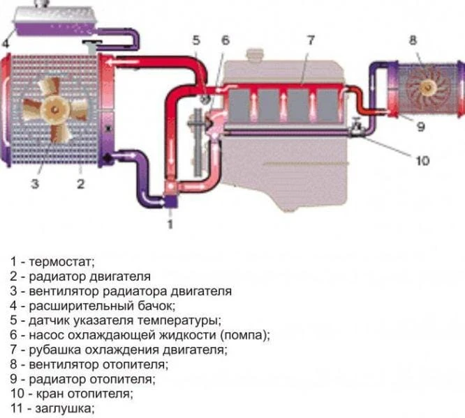
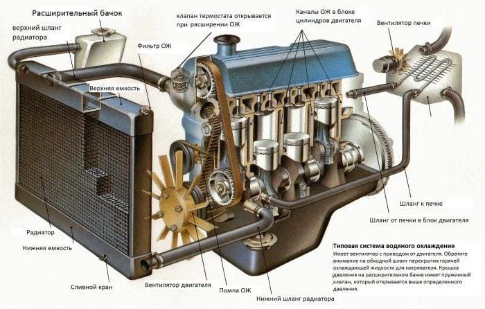
Scheme of the circulation of the coolant. Engine cooling system diagram
Every car uses an internal combustion engine. Liquid cooling systems are widely used – only on the old “Zaporozhets” and the new “Tata” air blowing is used. It should be noted that the coolant circulation scheme on all machines is almost similar – the same elements are present in the design, they perform identical functions.
Small cooling circle
In the scheme of the internal combustion engine cooling system, there are two circuits – small and large. In some ways, it is similar to human anatomy – the movement of blood in the body. The liquid moves in a small circle when it is necessary to quickly warm up to operating temperature. The problem is that the motor can function normally in a narrow temperature range – about 90 degrees.
You can not increase or decrease it, as this will lead to violations – the ignition timing will change, the fuel mixture will burn out of time. The circuit includes a radiator for the interior heater – after all, it is necessary that the inside of the car be warm as soon as possible. The supply of hot antifreeze is blocked with a tap. The place of its installation depends on the specific car – on the partition between the passenger compartment and the engine compartment, in the glove box area, etc.
Large cooling circuit
In this case, the main radiator is also included in the engine cooling system circuit. It is installed in the front of the car and is designed to urgently reduce the temperature of the fluid in the engine. If the car has air conditioning, then its radiator is installed nearby. On Volga and Gazelle cars, an oil cooler is used, which is also placed in front of the car. A fan is usually placed on the radiator, which is driven by an electric motor, belt or clutch.
Liquid pump in the system
This device is included in the Gazelle coolant circulation circuit and any other car. The drive can be carried out as follows:
- From the timing belt.
- From the alternator belt.
- From a separate belt.
The design consists of the following elements:
- Metal or plastic impeller. The efficiency of the pump depends on the number of blades.
- Housing – usually made of aluminum and its alloys. The fact is that this particular metal works well in aggressive conditions, corrosion practically does not affect it.
- The pulley for installing the drive belt is toothed or wedge-shaped.
- Shaft – a steel rotor, at one end of which there is an impeller (inside), and outside a pulley for installing a drive pulley.
- Bronze bushing or bearing – these elements are lubricated with the help of special additives that are available in antifreeze.
- The seal prevents fluid from leaking out of the cooling system.
Thermostat and its features
It is difficult to say which element provides the most efficient circulation of fluid in the cooling system. On the one hand, the pump creates pressure and the antifreeze moves through the nozzles with its help.
But on the other hand, if there were no thermostat, the movement would occur exclusively in a small circle. The design contains the following elements:
- Aluminum body.
- Outlets for connection with nozzles.
- Bimetallic type plate.
- Mechanical valve with return spring.
The principle of operation is that at temperatures below 85 degrees, the liquid moves only along a small contour. In this case, the valve inside the thermostat is in a position in which antifreeze does not enter the large circuit.
As soon as the temperature reaches 85 degrees, the bimetallic plate will begin to deform. It acts on a mechanical valve and opens access to antifreeze to the main radiator. As soon as the temperature drops, the thermostat valve will return to its original position under the action of a return spring.
Expansion tank
There is an expansion tank in the cooling system of the internal combustion engine. The fact is that any liquid, including antifreeze, increases volume when heated. As it cools, the volume decreases. Therefore, some kind of buffer is needed in which a small amount of liquid will be stored so that there is always plenty of it in the system. It is with this task that the expansion tank copes – the excess splashes out there during heating.
Expansion tank cap
Another indispensable component of the system is a cork. There are two types of construction – hermetic and non-hermetic. In the event that the latter is used on the car, the plug of the expansion tank has only a drain hole through which the pressure in the system is balanced.
But if a sealed system is used, then there are two valves in the plug – an inlet valve (takes air from the atmosphere inside, operates at a pressure below 0.2 bar) and an exhaust valve (operates at a pressure above 1.2 bar). It expels excess air from the system.
It turns out that the pressure in the system is always greater than in the atmosphere. This allows you to slightly increase the boiling point of antifreeze, which favorably affects the operation of the engine. This is especially good for driving in traffic jams in urban areas. An example of a sealed system is VAZ-2108 cars and the like. Leaky – models of the classic VAZ series.
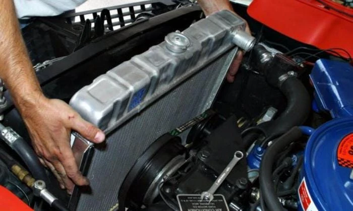
Radiator and fan
Coolant circulates through the main radiator, which is installed at the front of the vehicle. Such a place was not chosen by chance – when driving at high speed, the radiator cells are blown by an oncoming air flow, which ensures a decrease in engine temperature. A fan is installed on the radiator. Most of these devices are electrically powered. On Gazelles, for example, couplings are often used, similar to those that are placed on air conditioning compressors.
The electric fan is turned on using a sensor installed at the bottom of the radiator. The signal from the temperature sensor, which is located on the thermostat housing or in the engine block, can be used on injection machines. The simplest switching circuit contains only one thermal switch – it has normally open contacts. As soon as the temperature reaches 92 degrees at the bottom of the radiator, the contacts inside the switch will close and voltage will be applied to the fan motor.
Cabin heater
This is the most important part when viewed from the perspective of the driver and passengers. Comfort when driving in the winter season depends on the efficiency of the stove. The heater is part of the coolant circulation circuit and consists of the following components:
- Electric motor with impeller. It is turned on according to a special scheme in which there is a constant resistor – it allows you to change the speed of the impeller.
- The radiator is the element through which hot antifreeze passes.
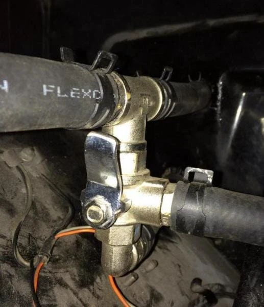
- Tap – designed to open and close the supply of antifreeze inside the radiator.
- The duct system allows you to direct hot air in the right direction.
The scheme of circulation of the coolant through the system is such that when only one inlet to the radiator is closed, hot antifreeze will not get into it in any way. There are cars in which there is no stove tap – there is always hot antifreeze inside the radiator. And in the summer, the air ducts simply close and heat is not supplied to the cabin.